
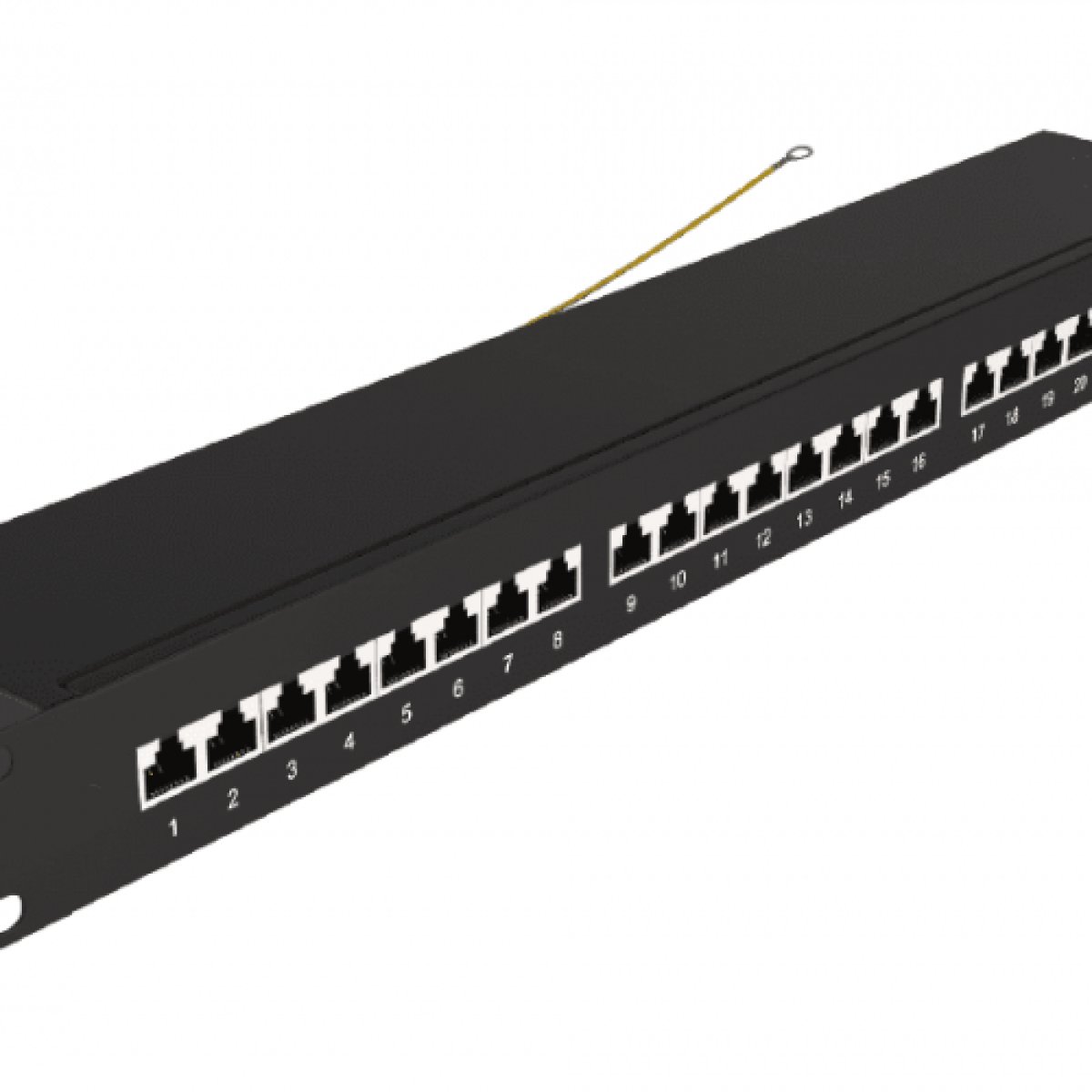
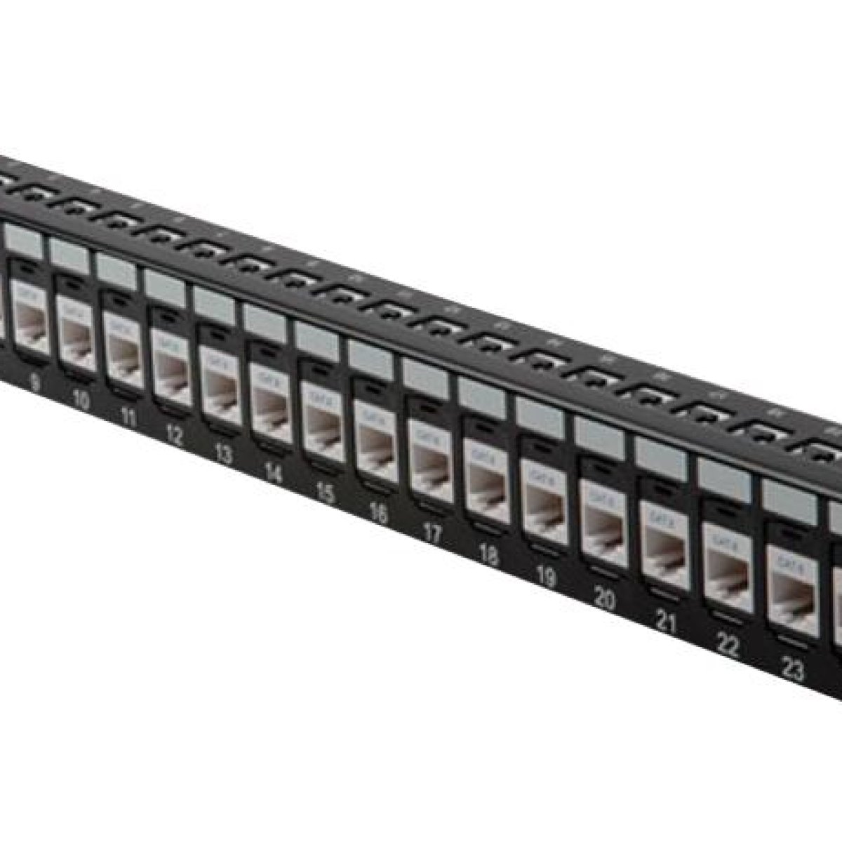
Structured Cabling Patch Panel A passive hardware network component engineered to centralize, organize, and terminate permanent structured cable runs inside an IT data closet. Mounted within standard 19-inch equipment racks, this panel bridges solid copper horizontal building cables (terminated via rear Insulation Displacement Connectors) with active network switch ports utilizing flexible front-facing RJ-45 patch cords—serving as the foundational cross-connect nexus for the facility's local area network (LAN).
The Foundational Architecture of Structured Cabling Networks
In a modern commercial facility, hundreds of copper data lines run through walls and ceilings to connect desktop computers, IP phones, wireless access points, and security cameras back to a central IT server room. Running these long, stiff cables straight out of the walls and plugging them directly into expensive active network switches introduces massive structural risks. Constant movement can wear down the internal copper pairs, leading to line failures hidden deep inside walls. A Structured Cabling Patch Panel solves this infrastructure problem by providing a rugged, static termination point for all permanent building wiring.
The patch panel operates completely within the passive layer of the network, requiring zero electrical power to function. The installation workflow relies on a clean, structural split-distribution layout:
The Permanent Link (Rear Side): Stiff, solid copper horizontal cables running from wall jacks throughout the building terminate directly onto the back of the patch panel. Installers use a punch-down tool to force individual insulated wires into specialized Insulation Displacement Connectors (IDC), usually arranged in standard 110-block styles. This creates a secure, gas-tight mechanical connection that never moves.
The Patching Matrix (Front Side): The rear connectors link directly through the panel’s circuit board to standard, numbered RJ-45 ports on the front face.
To bring a wall drop live, an IT technician runs a short, highly flexible stranded copper patch cord from the front of the patch panel to an open port on an adjacent active network switch. This layout means that whenever an office space is rearranged or a port is changed, all physical plugging and unplugging happens on the low-cost patch cables at the front of the panel, leaving the permanent wiring behind the rack completely undisturbed.
Key Performance Features
Substantial Network Cross-Connect Organization: Centralizes hundreds of complex cable runs into structured, numbered rows, making it easy for network technicians to trace lines, run tests, and reconfigure ports cleanly.
Preservation of Cable Geometry (Near-End Crosstalk Isolation): The internal printed circuit board (PCB) is engineered to maintain perfect wire twist ratios up to the exact point of connection. This minimizes Near-End Crosstalk (NEXT) and guarantees clean, high-speed data transfers up to Cat6A specifications ($10\text{ Gbps}$).
Dynamic Shielding Enclosure Armor: Available in fully shielded configurations featuring an integrated internal grounding bar and heavy steel casing blocks to insulate data packets from electromagnetic interference (EMI) caused by nearby fluorescent lights or high-voltage power lines.
Modular Keystone Customization: Available in blank modular arrays that accept individual snap-in keystone jacks. This allows engineers to mix copper RJ-45 lines, fiber optic couplers, and coaxial television lines cleanly inside a single rack frame.
Integrated Cable Strain Relief Bars: Outfitted with a heavy-duty rear steel shelf that accepts cable ties, supporting the physical weight of thick copper bundles and preventing gravity from pulling wires out of their punch-down slots over time.
Ideal Infrastructure Applications
Enterprise Corporate Data Centers: Organizing high-density vertical risers and horizontal copper runs across multi-rack networks.
Hospital & Healthcare Facilities: Structuring clean, electromagnetic-isolated data networks for sensitive medical equipment and floor-by-floor administrative pods.
Educational & University Campuses: Securing high-volume, easily reconfigurable terminal junctions capable of handling constant student layout adjustments.
Technical Performance MatrixEngineering Metric ParameterHigh-Spec Cat6A Shielded PanelStandard Cat6 Unshielded PanelCabling Performance StandardANSI / TIA-568.2-D Category 6AANSI / TIA-568.2-D Category 6 BaseTarget Bandwidth CapacityUp to 500 MHz FrequenciesUp to 250 MHz FrequenciesMax Network Transmission Speed10 Gbps ($10\text{GBASE-T}$) up to 100m1 Gbps ($100\text{BASE-T}$) nominal speedPhysical Interface Port Density48 Ports inside 1U or 2U Frame24 Ports inside 1U Component FrameRear Termination Blocks110-IDC Dual-Type Gas-Tight Blocks110-IDC Punch-Down Contact BlocksWiring Standardization MapsT568A / T568B Color-Coded MatrixT568A / T568B Color-Coded MatrixContact Plating Specification50 Micro-Inches Gold over Nickel15 Micro-Inches Gold Plating BaseElectromagnetic Shielding ModeFully Enclosed Shielded ($360^\circ$ STP)Unshielded Twisted Pair (UTP Profile)Hardware Form Factor Profile1U / 2U 19-Inch Rackmount Cold-Rolled Steel1U 19-Inch Rackmount Pressed SteelCompliance CertificationsUL Listed / RoHS / CE / ETL VerifiedCE / FCC ApprovedStandard Procurement Package Components
High-Density Structured Cabling Patch Panel Core Frame
Integrated Rear Cable Strain-Relief Support Bar
Heavy-Duty Nylon Cable Zip Ties and Velvet Cable Management Straps
Standard M6 Grounding Wire Strap Loop (For Shielded STP Models)
Equipment Rack Mounting Screw Sets and Cage Nut Assemblies
Clear Acrylic Snap-On Label Icons and Numbered Identification Strips